Measurement
Site preparation
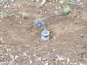
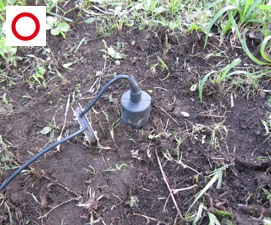
[1] Expose the ground surface.
At the point of measurement, remove dead leaves, grasses, grassroots, etc. around the pickup sensor, so that the ground surface is visible, and avoid contact of the sensor cable with grasses, etc. (thin grassroots can be scraped with the heel easily) (Photo 1).
[2] Site preparation for the ground surface
In order to ensure good contact at the bottom of the pickup sensor, solidify the ground by stamping on it and make it flat (Photo 1).
(The preparation work may be omitted if the soil ground is hard enough and the contact can be maintained.)
Distinguishing sound by listening to it
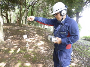
Some users advise us when using the device for the first time, asking "I don't know which is the groundwater aeration sound." It is easier to distinguish the groundwater aeration sound if the sound is compared with the white noise given off by the main body.
As indicated in the photo, make the pickup sensor come to a standstill in the air, and [1] listen to the white noise given off by the main body. Next, [2] insert the pickup sensor into the soil ground, and listen to the groundwater aeration sound. The difference in sound between [2] and [1] becomes the groundwater aeration sound that has been transmitted to the soil ground. Let's distinguish the white noise and groundwater aeration sound by listening to them (Photo 2).
[1] White noise
Suspend the acceleration sensor in the air and let it come to a standstill, and listen to the sound at that time.
The sound "shaa..." is the white noise.
[2] Groundwater aeration sound
Now, insert the pickup sensor into the ground and listen to the sound again. Aside from the white noise "shaa..." that was heard in the air, burbling or trickling sounds is heard. This sound is the groundwater aeration sound.
Note that the movement of the person making measurement itself becomes the cause of noise, and so when listening to the sound by inserting the pickup sensor into the ground, the person making measurement should make his or her body come to a standstill.
Sound sources of white noise and groundwater aeration sound


Installation of a pickup sensor
[1] Fit the sensor rod
Select the sensor rod according to the hardness of the soil ground or the thickness of the soil layer at the site.
■Types of sensor rod
- Large (20 cm): For soft ground where contact of the sensor bottom cannot be maintained
- Medium (15 cm): Standard; for ordinary soil ground
- Small (10 cm): For soil ground with a shallow soil layer (sprayed materials on a slope, and the like)
- Sensor disc: A place where there is no soil such as a rock bed or asphalt (the sensor disc is an optional item to be purchased separately)
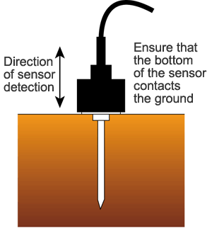
[2] Insert the pickup sensor into the ground surface
Since vibration is sensed at the bottom of the pickup sensor, install the pickup sensor so that its bottom contacts the ground securely.
* Since the pickup sensor captures vibration in the vertical direction, the pickup sensor should be installed in the vertical direction as a general rule.
* Avoid contact of grasses, etc. to the pickup sensor because any such contact becomes the cause of noise.
* The antivibration plate should be fixed to the ground. Take measures so that no cable noise is picked up.
* Right after inserting the pickup sensor into soft soil ground, a force of the ground for returning its original state works. Due to this force, the soil ground vibrates and a sound similar to the groundwater aeration sound may be heard. In this case, wait for a while and after the vibration of the soil ground has ceased, start measurement. Such vibration can be diminished by stamping the ground well at the time of site preparation.
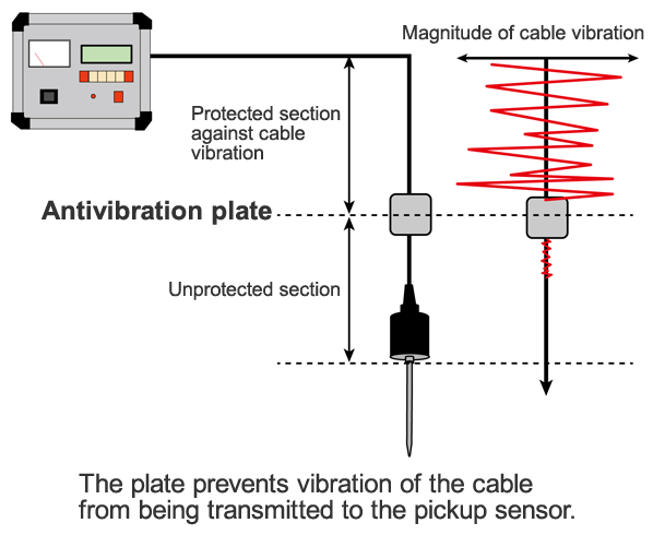
Role of the antivibration plate
If the cable of the pickup sensor vibrates, such vibration is transmitted to the pickup sensor and becomes noise.
Because of this, the antivibration plate is used to prevent vibration coming from the cable from being transmitted to the pickup sensor.
Since noise cannot be removed in the unprotected section, installation should be done in the correct method of installation.
Correct method of installation of the pickup sensor
- Install the pickup sensor so that its bottom contacts the ground securely.
(The sensor rod is used to fix the sensor to the ground, and is not a vibration detector.) - Remove anything that become the cause of noise from the areas around the pickup sensor (unprotected section).
- Prevent the cable from tangling.
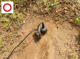
An example of correct installation
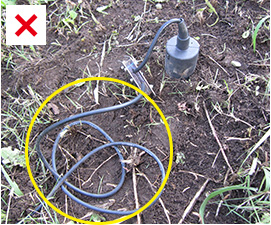
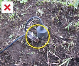
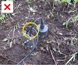
Examples of incorrect installation of an incorrect pickup sensor
[1] Avoid contact of the pickup sensor or antivibration plate with grasses, dead leaves, or the like. Grasses, etc. are swayed with wind, and vibration becomes the cause of noise.
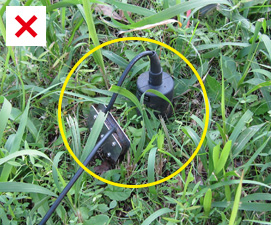
[2] Avoid tangling of the cable. Tangling of the cable gives rise to noise.
[3] Prevent contact of the pickup sensor with the antivibration plate. Swaying of the antivibration plate gives rise to noise.
[4] Eliminate any twisting of the cable. It causes a rubbing of the cable, resulting in noise.
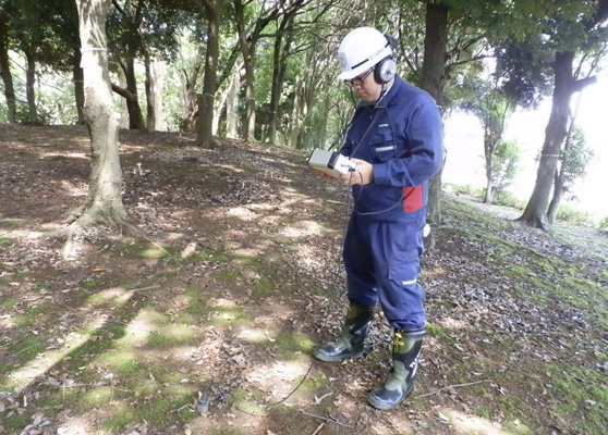
Posture at the time of making measurement
Measurement should be made in a posture of standstill. Since any body movement results in vibration noise in the pickup sensor, measurement should be made in a posture of standstill by keeping the width between the feet roughly to a shoulder width (keeping the body standstill is easier by stopping breathing for a while). Also, if it is difficult to come to a standstill on a slope, etc., vibration is unlikely to occur by sitting on the ground.
Recording and organizing of the position of measurement by means of GPS
The groundwater aeration sound measuring device has no functions of recording the position (latitude/longitude) of the place of measurement. Here, explanations are given about the method of preparation of a "groundwater path estimation map" that shows the position of the groundwater path on a map by recording the position of the place of measurement by separately preparing a small GPS terminal that has excellent portability.
Overview
We recommend the use of a GPS terminal manufactured by GARMIN because it can ensure accuracy of around several meters in an environment such as a forest where it is difficult to receive signals from satellites and besides it is inexpensive. Here, explanations are given by using the company's eTrex30 as an example.
Note that a GPS terminal of any other company may be used, but the terminal needs to be ready for use with the satellites of the United States (GPS), Russia (GRONASS) and Japan (Michibuki+α).
Operating procedures of the GPS terminal
1. Preparation for measurement
[1] Turn on power for the GPS terminal.
[2] Select "Settings" → "System" from the main menu, and set the satellite receiving mode into "GPS+GLONASS."
And set "MSAS / WAAS" to ON.
* The above settings increase accuracy.
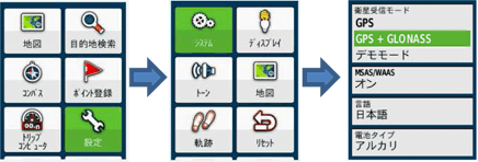
[3] Select "Satellite Information" from the main menu, and check the captured satellite.
* Attention should be paid to the fact that accuracy decreases when the number of captured satellites is small.
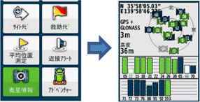
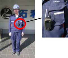
[4] The GPS terminal should be placed at a position as high as possible when making measurement. A high position makes it easier for the terminal to receive GPS signals, thus increasing the accuracy of measurement.
2. Measurement of the position
[1] Record the latitude/longitude of the position of measurement by selecting "Average Position Measurement" → "Point Creation" → "Store" from the main menu.
* Accuracy increases as a result of making measurement of the average position.
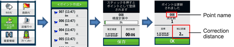
[2] In order to match the position of measurement with that of the measurement data with the groundwater aeration sound measuring device later on, write down the "point name" and "correction distance" that are displayed on the screen on the field book, etc.
* Regarding the "Accuracy being calculated," 100% is recommended.
However, since measurement may take time depending on the state of receiving of the satellite, on such an occasion, halfway termination/finalization may be done after around 1 minute of the measuring time although the accuracy of the position of measurement decreases.
* If the "correction distance" is 5 m or more, the measurement should be continued.
(The correction distance will be used as a value for reference purposes when making correction of the position of measurement on software.)
3. Measurement of groundwater aeration sound
[1] Make measurement for the groundwater path by referring to the "Simplified Method of Operation of the Groundwater Aeration Sound Measuring Device."
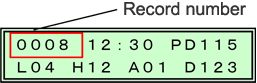
* In order to match the data of the position of measurement that has been recorded with the GPS terminal with the position of measurement of the measured data with the groundwater aeration sound measuring device later on, write down the "record number indicated on the screen of the groundwater aeration sound measuring device" on the field book, etc.
Matching the positions of the measured data on the GPS terminal and on the groundwater aeration sound measuring device
1. Preparations for taking in the measured data
[1] Install the map data control software BaseCamp to a PC in accordance with the operation manual for the "Japanese Mountains Climbing Map TOPO10M PlusV2."
2. Creation of a groundwater path estimation map by taking in the measured data and by means of positioning
[1] Start the BaseCamp.

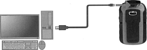
[2] Connect a PC to the GPS terminal by using the dedicated USB cable.
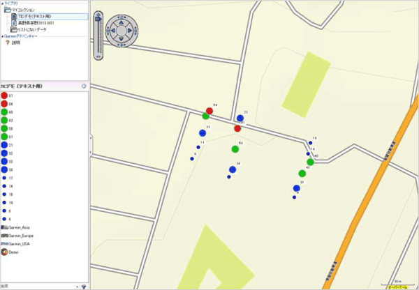
[3] The GPS device appears on BaseCamp, and by selecting the "Built-in memory," the position where measurement was made is plotted on the map.
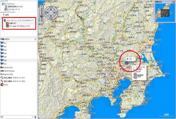
[4] Select the position of measurement that has been plotted, and change the name at the "Memo" tab to the measured data (Typical Value (D)) of which "Record Number " on the groundwater aeration sound measuring device matches with the "Point Name (the number indicated in the name at the "Memo" tab)."
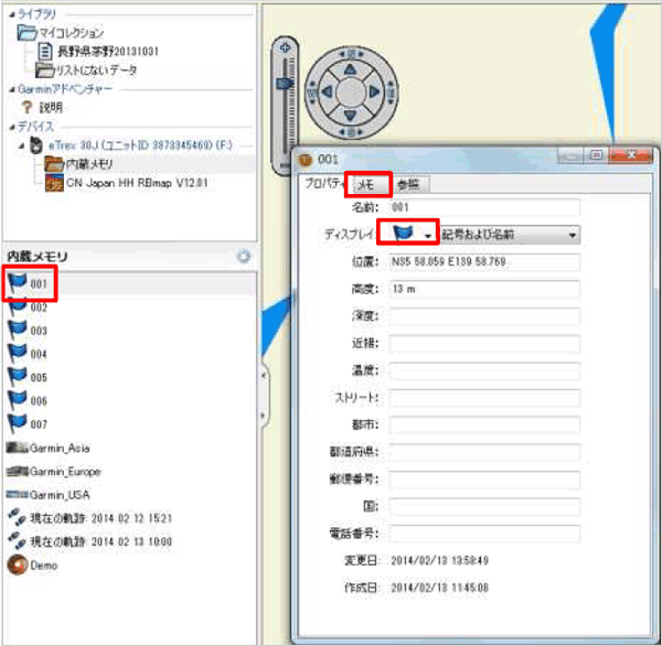
[5] On the display at the "Memo" tab, the mark can be changed according to the value of the Typical Value (D), and so set the size and color code for the mark here. Based on the result of this operation, a place where the large values of Typical Value (D) concentrate is indicated on the map, and a groundwater path is estimated.
* For the details of the method of operation, etc., check the operation manual for the Japanese Mountains Climbing Map TOPO10M PlusV2.