Device settings
Device settings
Contents of indication on the basic screen
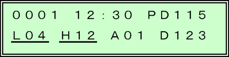
The basic screen indicates the present time, data of the groundwater aeration sound being input, and at the same time it indicates the setting values for the basic conditions of measurement (frequency filter, degree of amplification) as well.
On the basic screen, the "frequency filter settings" and "settings for change in the degree of amplification" that are changed frequently when measuring groundwater aeration sound can be changed easily by means of switch operation.
Also, by pressing the RECORD switch on this screen, measurement of the groundwater aeration sound and a recording of the measured data can be made.
After having turned on the power, the title screen is displayed for about 2 seconds, and then the basic screen is displayed (Fig. 1).
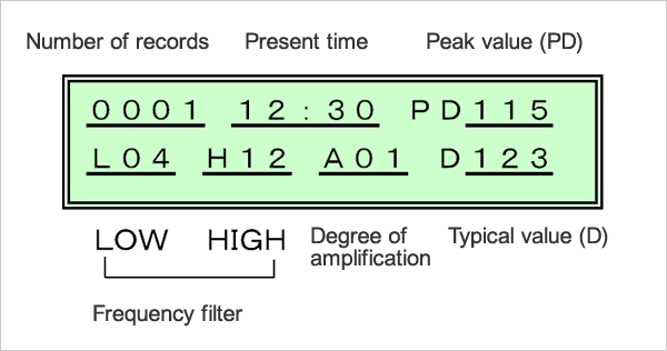
- Number of records:It shows the number of the data recorded inside.
- Present time (hour: minute):It shows the present time.
- Peak value (PD):It is a peak value for each time of measurement that is used to calculate the typical value (D). It is the value that was calculated in the primary processing.
- Frequency filter (LOW):It is the setting value of the frequency low cut filter that has been set at the present. Input signals of any frequency below the value set here are cut.
- Frequency filter (HIGH):It is the setting value of the frequency high cut filter that has been set at the present. Input signals of any frequency above the value set here are cut.
- Degree of amplification:It is the degree of amplification that has been set at the present. It is the loudness of the signal that has been input.
- Typical value (D):It is the data that becomes representative that has been calculated in the peak value (PD) for each time of measurement. It is the value that was calculated in the secondary processing.
Change in the degree of amplification (sound loudness)
≫Explanations of the degree of amplification
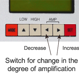
Change in the degree of amplification for signals that have been captured in the pickup sensor is made by means of operation on the basic screen.
The number on the right side of "A" in the indication on the basic screen represents the setting value of the degree of amplification.
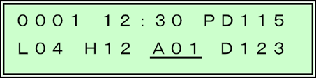
· A01: It shows that the degree of amplification is set to 1.
[1] Change in the degree of amplification
[1] Change in the degree of amplification
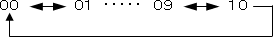
Each time when the ◀ switch is pressed, the number at A decreases by 1, and each time when the ▶ switch is pressed, the number at A increases by 1.
* If the degree of amplification is set to 0, each of the level meter value, peak value (PD) and typical value (D) is set to the value of 0, and the output of the headphone is set to the loudness of 0.
* If the degree of amplification is increased too much, a loud sound may be output from headphone, against which caution should be exercised.
[2] Memorization of the setting values
The setting value of the degree of amplification can be changed promptly by means of switch operation, but if power is turned off, the change is not memorized.
If the setting value that has been changed should be memorized, press the SET switch.
The contents of change is memorized in the non-volatile memory, and the contents of the memory remain even if power is turned on or off.
* The filter setting values in the preceding section are also memorized together.
* If any change has been made to the filter and the degree of amplification, erase the PD value once, and then after about 0.5 seconds, start the calculation of the peak value (PD) and the typical value (D) newly.
Change in filter settings
The settings of filter functions for the signals captured with the pickup sensor are made by operation on the basic screen. "L" on the indication of the basic screen means the low cut filter, and "H" means the high cut filter, and the number on the right represents the frequency of the filter that has been set.
· L04: It means that the low cut filter is set to 400 Hz.
· H12: It means that the high cut filter is set to 1200 Hz.
The number on the screen is indicated by omitting "00" in the last 2 digits of the actual frequency.
The correlation with the frequency that has been actually set becomes as follows.
| Low cut filter | High cut filter | ||
|---|---|---|---|
| Indication | Frequency (Hz) | Indication | Frequency (Hz) |
| 00 | 0 | 00 | 0 |
| 02 | 200 | 06 | 600 |
| 03 | 300 | 08 | 800 |
| 04 | 400 | 12 | 1200 |
* 0 Hz means that no filter settings are made.
Settings for the filters are made by means of operation of ▲・(LOW) and ▼ (HIGH) switches.
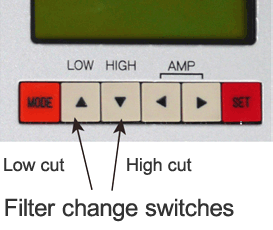
[1] Change in the low cut filter
Each time the ▲ (LOW) switch is pressed, the number at "L" changes as follows, and the setting value of the low cut filter is changed according to the number.
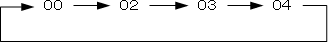
[2] Change in the high cut filter
Each time the ▼ (HIGH) switch is pressed, the number at "H" changes as follows, and the setting value of the high cut filter is changed according to the number.

[3] Memorization of the setting values
Change in the filter setting values is applied promptly when they have been changed by switch operation, but the change is erased if power is turned off.
If the value that has been changed should be memorized, press the SET switch. The contents of change is memorized in the non-volatile memory of this device, and the contents of the memory remain even if power is turned off.
* The value of the change in the degree of amplification in the preceding section is also memorized together.
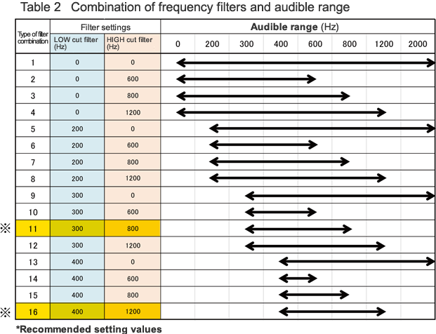
* Recommended setting values (indicated in the table in yellow)
LOW cut filter: 300 (or 400), HIGH cut filter: 800 (or 1200)
Degree of amplification: 5, Number of samples: 100, Average number of data: 3